Teardown: Rivian R1S Autonomy eXperience Module (AXM) 1.0
Introduction
Welcome to another infotainment device teardown! Today we’ll be performing a teardown and analysis of the Rivian “Autonomy eXperience Module”, or AXM.
The AXM is a core part of the Rivian R1S and R1T vehicles, controlling driver assistance, media playback, infotainment display, and essentially all ADAS/infotainment tasks in the vehicle!
As a short introduction to Rivian: Rivian is a relatively new electric vehicle company, with their first vehicles rolling off production lines in late 2021, only 5 years ago! This AXM was sourced from a crashed 2022 Rivian R1S making it a relatively early revision, historically-speaking.
In an actual vehicle, this module would be found in the front of the passenger-side footwell, tucked up and into the dashboard, similar to where Telsa's watercooled infotainment systems are installed.
The specifics of this module are as follows:
Production Date: 2022-02-31
Part Number: PT00001493-M
Without further ado, lets dive in!
High Level Overview
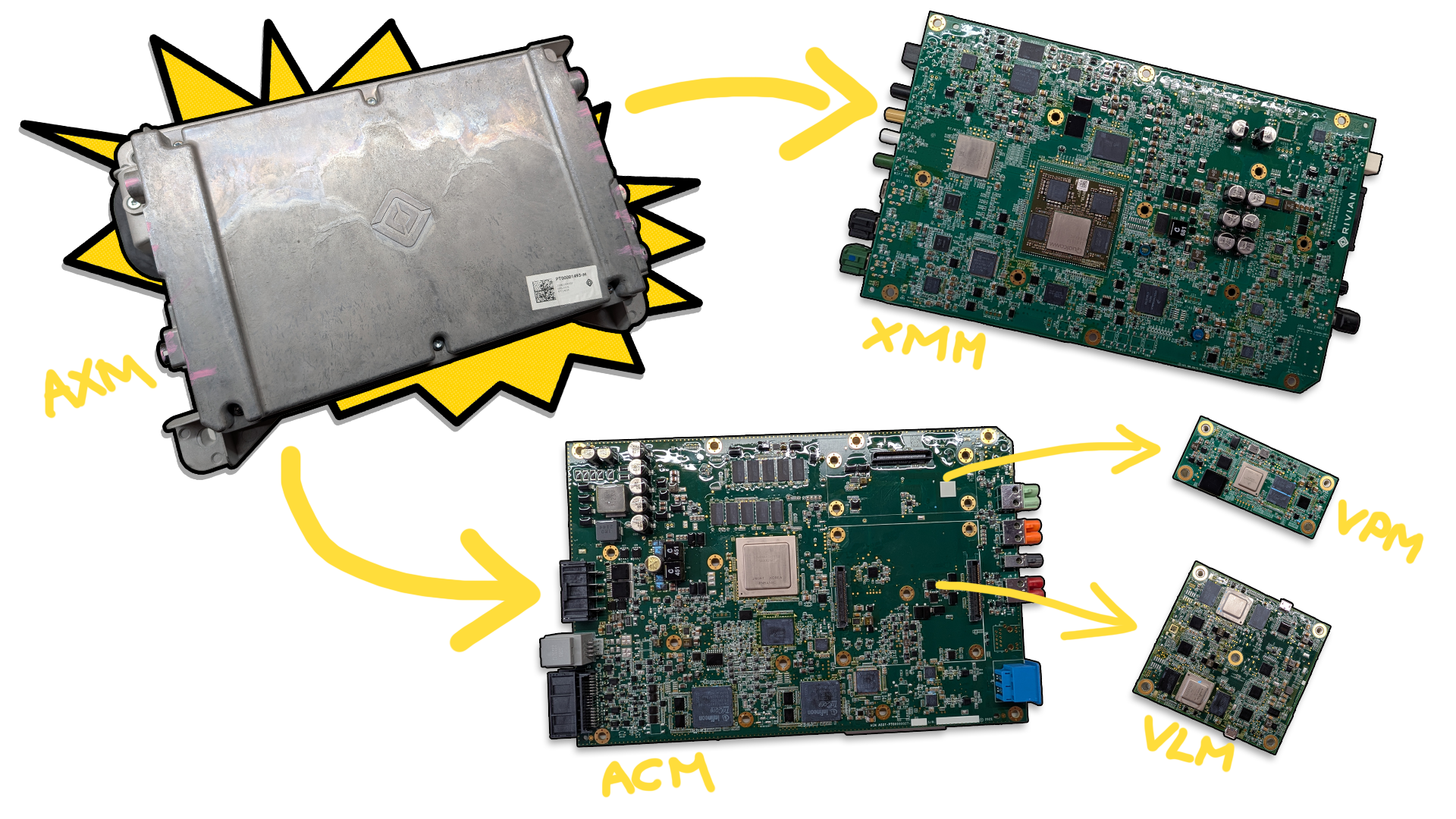
The AXM is a unique module, being comprised of two essentially-separate systems that operate out of the same enclosure. One system for infotainment, one for ADAS.
In total, the AXM is comprised of four PCBs - two main PCBs, and two daughterboards:
XMM - eXperience Management Module - Infotainment Functionality
ACM - Autonomy Control Module - ADAS Functionality
VLM - Camera/Video Processing (Daughterboard)
VPM - Camera/Video Processing (Daughterboard)
The XMM PCB controls all of the infotainment-related functionaltiy, while the ACM PCB controls all of the ADAS functionality. The ACM PCB also has two smaller daughter boards installed on it for video processing: The VLM, which processes mirror and front camera data, and the VPM, which processes fender camera data.
This particular AXM represents the first generation of AXM, or 'AXM 1.0'. Newer Rivian vehicles (2024+) offer the AXM 2.0, which features an entirely different layout with a completely revised XMM and ACM PCB. Soon, Rivian will be offering the upcoming AXM 3.0, which is slated to use Rivian's own custom silicon for the main processors! (I'm excited to tear one of those down in the future)
Basic Specs
Because each of the PCBs in this unit are jam-packed with components, coming up with a basic 'spec list' isn't as easy as with other modules! To make the data a bit less overwhelming, I've separated the AXM's spec list into two separate spec sheets - one for the XMM, and one for the ACM.
As always, for exact part numbers and info, check the 'Inside the Module' teardown section, or the full dump in the Appendix at the end! This is just a high-level overview :)
ACM Basic Specs
Processors
Main Processor: NXP Layerscape 64-bit 8-core ARM Cortex-A72 Microcontroller
10GB Micron DDR4 SDRAM
2x TriCore TC299TX Processors
16MB SRAM each
Storage
512GB Micron NVMe SSD
125MB Micron NOR Flash
Connectivity
2x Automotive Ethernet PHYs
Automotive Ethernet Switch
Sensors
Murata Gyroscope + 3-axis Accelerometer
XMM Basic Specs
Processors
Main Application Processor: Qualcomm SA8155P Processor
12GB Micron LPDDR4 RAM
VIP Processor: NXP MPC5746C
3MB on-chip flash memory
Ambarella Camera Processor
2GB Micron LPDDR4 RAM
Storage
128GB Kioxia UFS Storage
32GB Micron eMMC Storage
32GB Micron NAND Flash
512MB Micron NAND Flash
Connectivity
Bluetooth + Dual WiFi Transceiver
CAN 2.0/CAN-FD
Dual Gigabit Automotive Ethernet
Automotive Audio Bus (A2B)
FPD-Link III, GMSL2
Outside of the Module
The Rivian AXM module, as seen from the front.
Behold - the giant chunk of metal. On the front of the module, there isn't much to see - a Rivian logo! That's about it.
The back side of the AXM unit.
Flipping the unit over to the back, you can ignore the yellow writing - I believe it was written on by the parts seller I bought the unit from.
The outside of the module doesn't have much going on, but the water cooling is pretty cool! This module is intended to have coolant passing through it when running, allowing the unit to be water-cooled with no fans or moving parts.
The water cooling hook-up points on the back of the module.
Module Connectivity (I/O)
A quick peek around the sides allows us to view the I/O, which is present on both the left and right edges of the unit. I’ve gone ahead and labeled all of the known connectors with their use and PCB silkscreen marking (ie: J16, J17, etc.)
The unit is pretty light on external labeling, but we’ll dive into that next!
Top Label Information
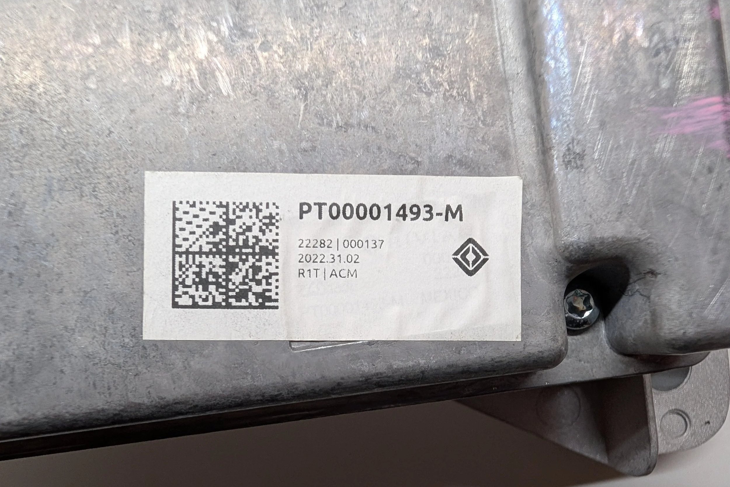
The AXM’s top label, showing the device’s part number and manufacturing date.
It may not be obvious at first glance, but the label present on my unit is kinda… weird. For context, let me show what a newer Rivian part label looks like:
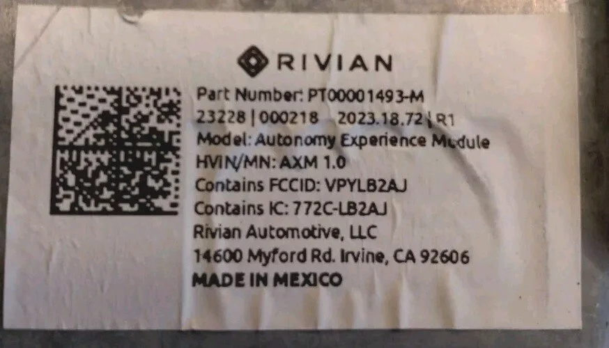
The top label off of an AXM unit built a year later, in 2023.
As you can see, lots of detailed information! But looking at the sticker on my unit, it’s extremely minimal by comparison. It doesn’t have the unit’s model name, HVIN, FCC ID, IC, Rivian’s address, or the “Made in Mexico” marking.
For now, my best guess is that this has to do with Rivian’s part shortage and production woes in the early days of their vehicle production.
Maybe early in the build process they forgot some of this detailed information on parts labels, and those parts ended up going out to consumers? (But also, I think not properly declaring the FCCID of the transmitter inside of the unit might garner some sort of FCC fine... :O uh oh)
Side Label Information
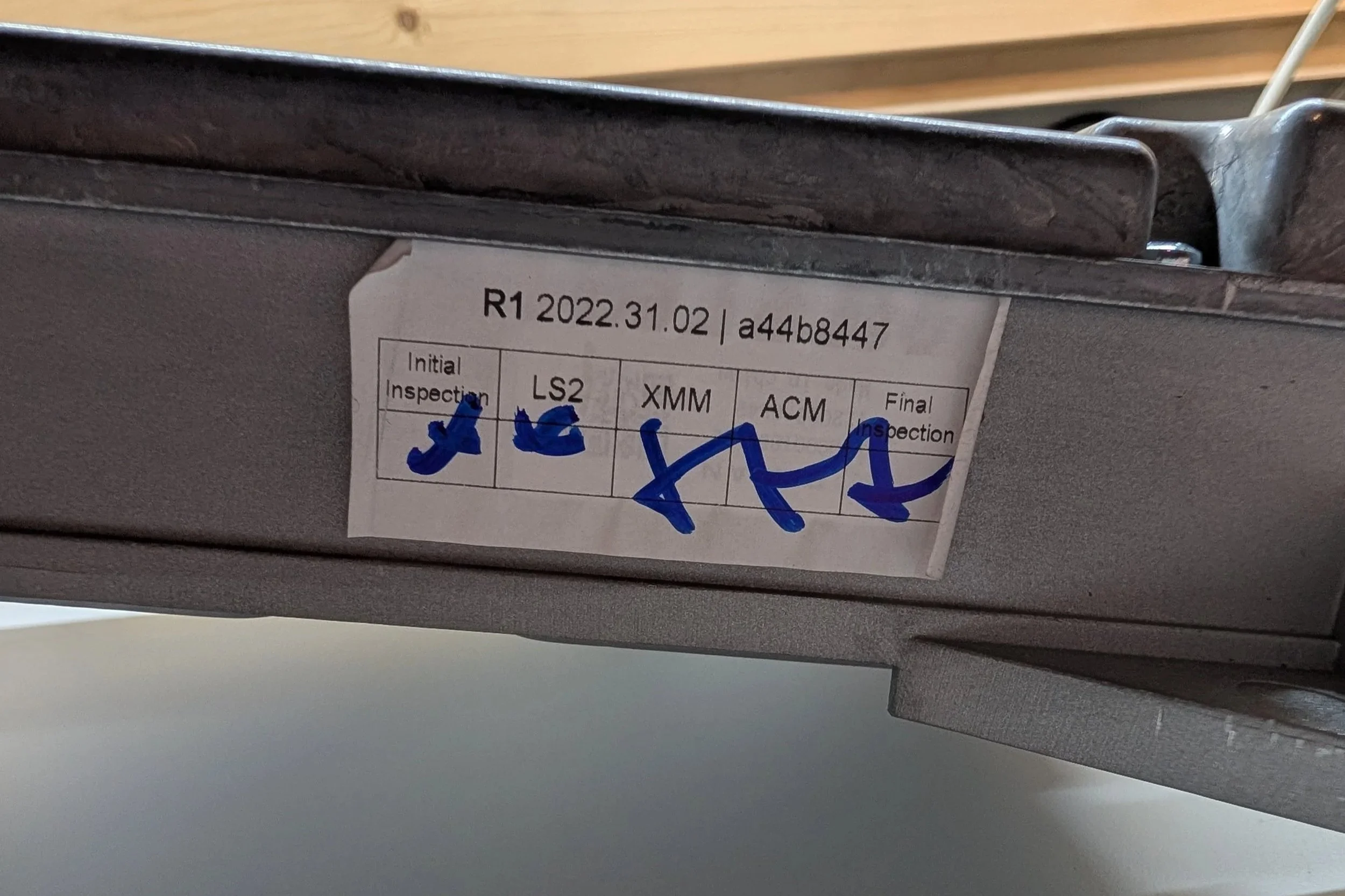
The inspection label, found on the bottom edge of the unit.
The second label can be found on the bottom edge of the unit. This seems to be a basic QA inspection label, showing that each portion of the module was inspected for quality assurance. The date on the sticker is likely the date of the inspection, but I’m unsure about the short hash/identifier - perhaps an internal lookup ID of some sort.
Inside the Module
Next, we’ll dive inside!
As stated in the intro, the AXM is made up of four total PCBs - two main PCBs, and two daughterboards. The main PCBs flank either side of the water cooling plate that runs down the center of the enclosure. One side holds the XMM PCB, and one side holds the ACM PCB.
Popping off the first side cover (with the Rivian logo), we get: The XMM PCB!
A first look at the XMM PCB, as seen when removing the unit’s outer cover.
This side of the XMM PCB doesn’t have much going on - mainly just I/O! Most of the fun (and heat-generating) components are on the opposite side of the board, where they can get nice and cozy with the water block in the center of the unit.
Flipping the AXM over, we can remove the second cover and find: The ACM PCB!
A first glance at the ACM PCB, located on the opposite side of the AXM.
Just like with the XMM PCB, the side of the ACM PCB that we’re greeted with is pretty boring! All of the fun components are on the inside, pressed up against the water block for the best cooling.
Just for fun, before we dive into the individual PCBs, lets take a look under the PCBs
The bare enclosure and water block, showing the twisting passage that coolant takes through the module.
This is what the enclosure/water block looks like with the PCB removed. The blue bits are thermal compound to help transfer heat between the ICs and the heat sink. As a little bonus, we can also spy some nice machining… Anyways, on to the individual PCB analysis!
XMM PCB
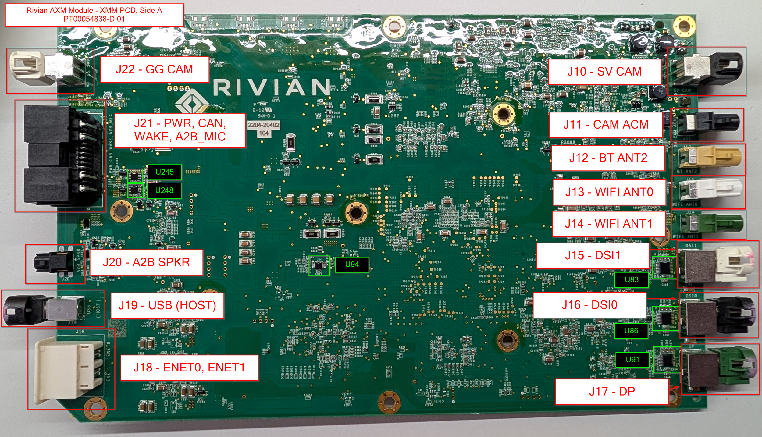
The AXM PCB, Side A.
We'll start with the XMM PCB, since that's the board we opened up to first. This PCB controls the full multimedia experience in the vehicle, and has a wide variety of IO.
XMM PCB Board Markings:
2204-20402 104
PT00054838-D 01
(C) 2021 XMM SA8155 X5
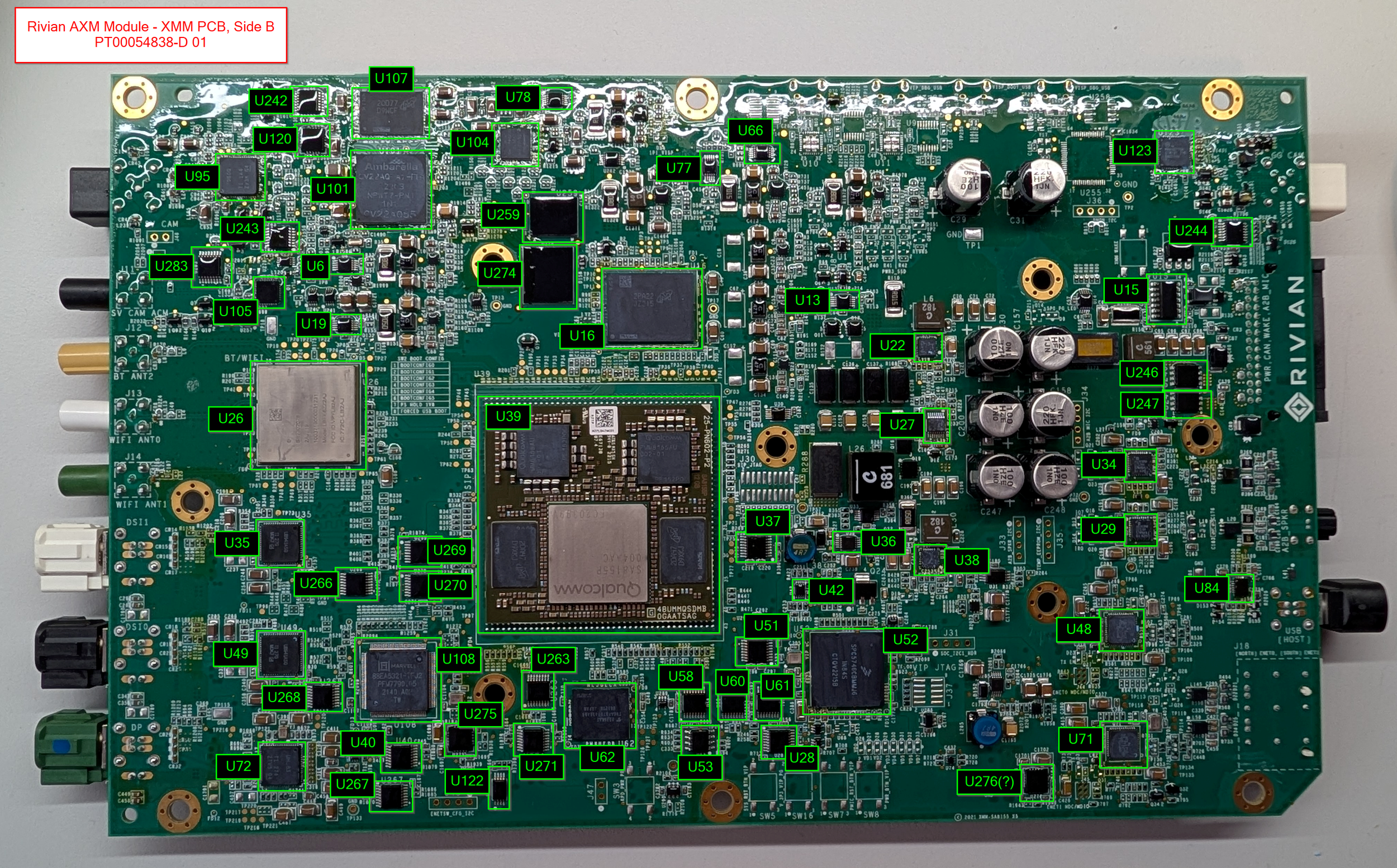
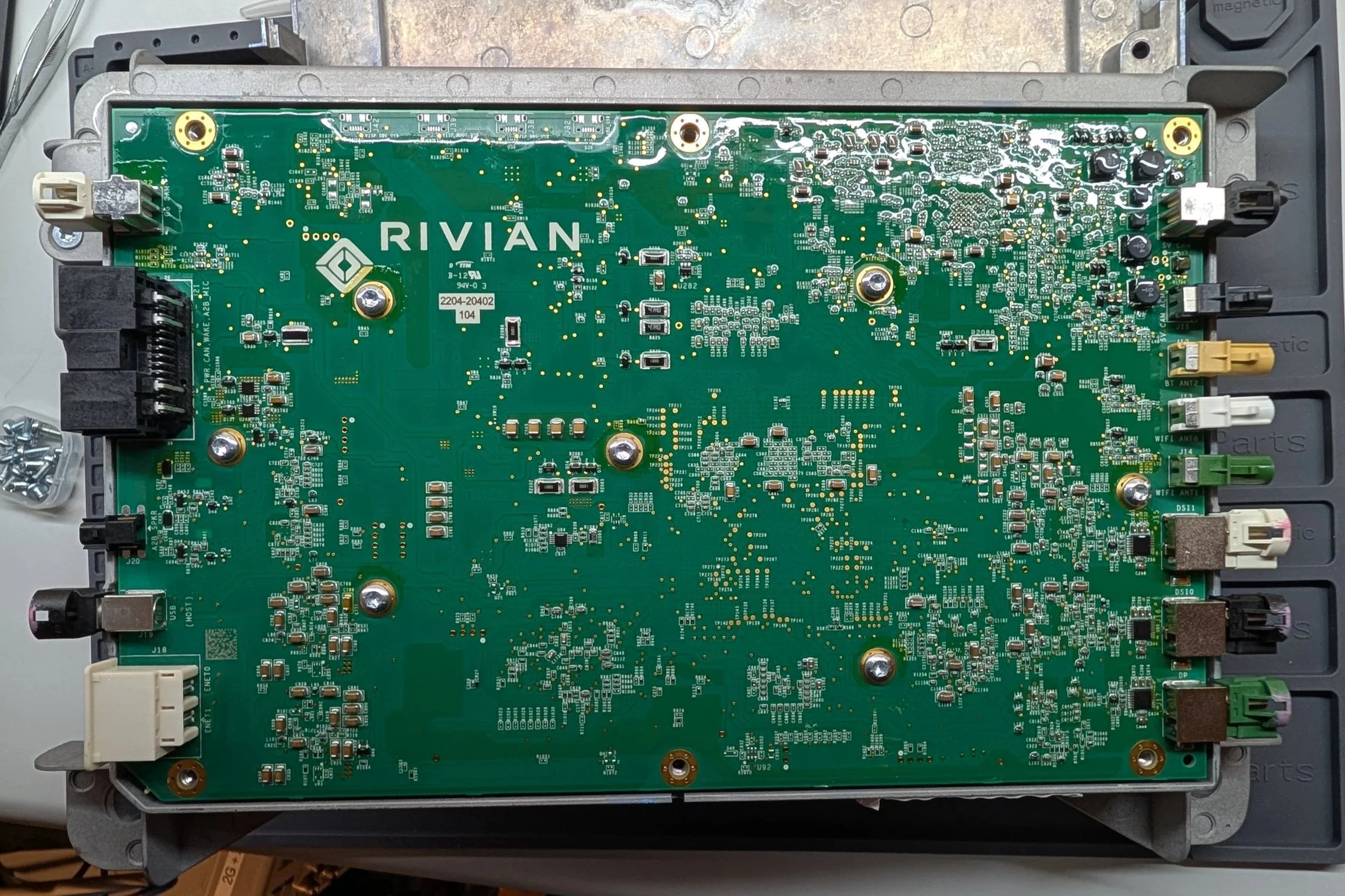
The XMM PCB, Side B.
The back side of the PCB is where all of the fun is hiding. The board's main application processor is a Qualcomm Snapdragon SA8155P with 12GB of DDR4 RAM - not bad specs at all!
As we start diving in, you can also see something else I really like about these PCBs: The insane amount of silkscreen labeling and test points! I think these boards will be quite easy to diagnose and repair in the future, just due to the prevalence of helpful markings, test points, etc. - I haven’t seen this on the other infotainment PCBs that I’ve poked at in the past.
Side note, some may wonder: Doesn’t this defeat any security by obscurity, making the PCB easier to reverse engineer/attack?
To that, my counter point would be: If the only thing stopping someone from hacking your module was the lack of PCB silkscreen markings, you never had security - and it would only be a matter of time before someone figures that out!
Dedicated attackers are, well, dedicated. I think having a strong security model + good silkscreen markings can help ensure that your modules are repairable and don’t turn into e-waste, while not having to hide behind security by obscurity for your defenses.
The XMM PCB’s main SoC, the Qualcomm SA8155P.
This module performs the actual display output to the variety of screens in the vehicle, as well as processing the data for a few different camera feeds. Couple that with some Bluetooth, WiFi, Ethernet, and USB, and it's got essentially the full infotainment package!
XMM - Connectivity
As expected, this board is pretty heavy on video processing. Connectivity for this board includes:
Surround-view camera feed
“Gear Guard” camera feed
Video output to the…
Instrument Cluster (DSI1)
Center Display (DSI0)
Rear HVAC Display (DP)
Bluetooth
2x WiFi Antennas
USB
Dual Gigabit Ethernet
A2B Audio (Automotive Audio Bus)
XMM - Component Overview Diagrams
I’m trying something a little new in this blog post - I put together these component overview diagrams, where I tried to identify and label each of the components that I could find. Hopefully they come in handy! :)

XMM PCB, Side A - With all I/O labeled
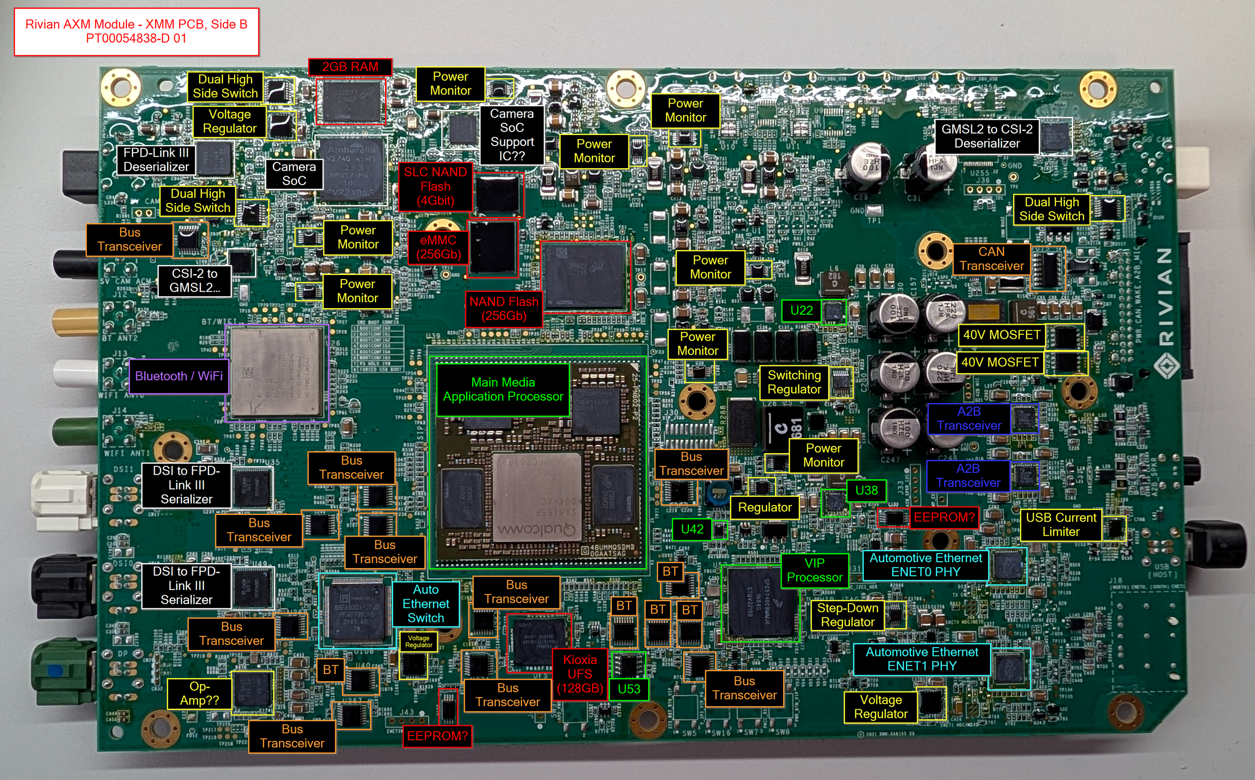
XMM PCB, Side B - With all components labeled
XMM - Major Components
The list below has the main components found on the XMM PCB. For a list of all of the components I've identified, check the Appendix at the bottom of the post!
Processor:
Qualcomm SA8155P SoM (datasheet)
Silkscreen Markings:
48UMMQSDMB 0GAATSAG
SA8155P 12G
Micron 6GB LPDDR4 RAM (2x, 12GB RAM Total) (datasheet)
2DA47 D9XKJ
MT53E1536M32D4DT-046 AIT:A
Qualcomm PMM8155AU 002-01 (x2)
I believe these are proprietary Qualcomm power management ICs created for the SA8155P package, from what I could find on the internet.
Storage:
Kioxia UFS Storage (128GB) (datasheet)
THGAF8T0T43BAB8
Or maybe THGAF8T0T43BA88?
I think this is 128GB in size, but I couldn't find the exact part number in this datasheet
Micron Automotive NAND Flash SSD (Likely 256Gb) (datasheet)
Micron 2PA22 JZ215
Decoded part number: MTFDHBL256TDQ-1AT12ATYY
Datasheet is restricted access :(
Micron Automotive MLC eMMC (256Gb) (datasheet)
Micron 2CA2D JWD43
Decoded part number: MTFC32GAPALGT-AAT
Micron Automotive SLC NAND Flash (4Gbit) (datasheet)
Micron 2NFID NW945
Decoded part number: MT29F4G08ABAFAH4-AAT:F
Networking:
muRata Bluetooth/WiFi IC (datasheet)
SS2302028
Model: LBEE6ZZ2AJ
FCC ID: VPYLB2AJ
IC: 772C-LB2AJ
Marvell Automotive Ethernet PHY (ENET0 and ENET1) (datasheet)
Marvell Q2112-NYD2
100/1000BASE-T1 (100mbit -> 1gbit auto ethernet)
Marvell Automotive Ethernet Switch (datasheet)
Marvell 88EA6321-TFJ2
7-port Ethernet Gigabit-capacity Switch
TI TCAN114x-Q1 CAN FD Transceiver (datasheet)
TI 21634/K
Video Processing:
Ambarella Automotive Camera SoC (datasheet)
Ambarella CV22AQ-A1-RH
Unfortunately, the real full datasheet is locked behind registration paywalls
ACM PCB
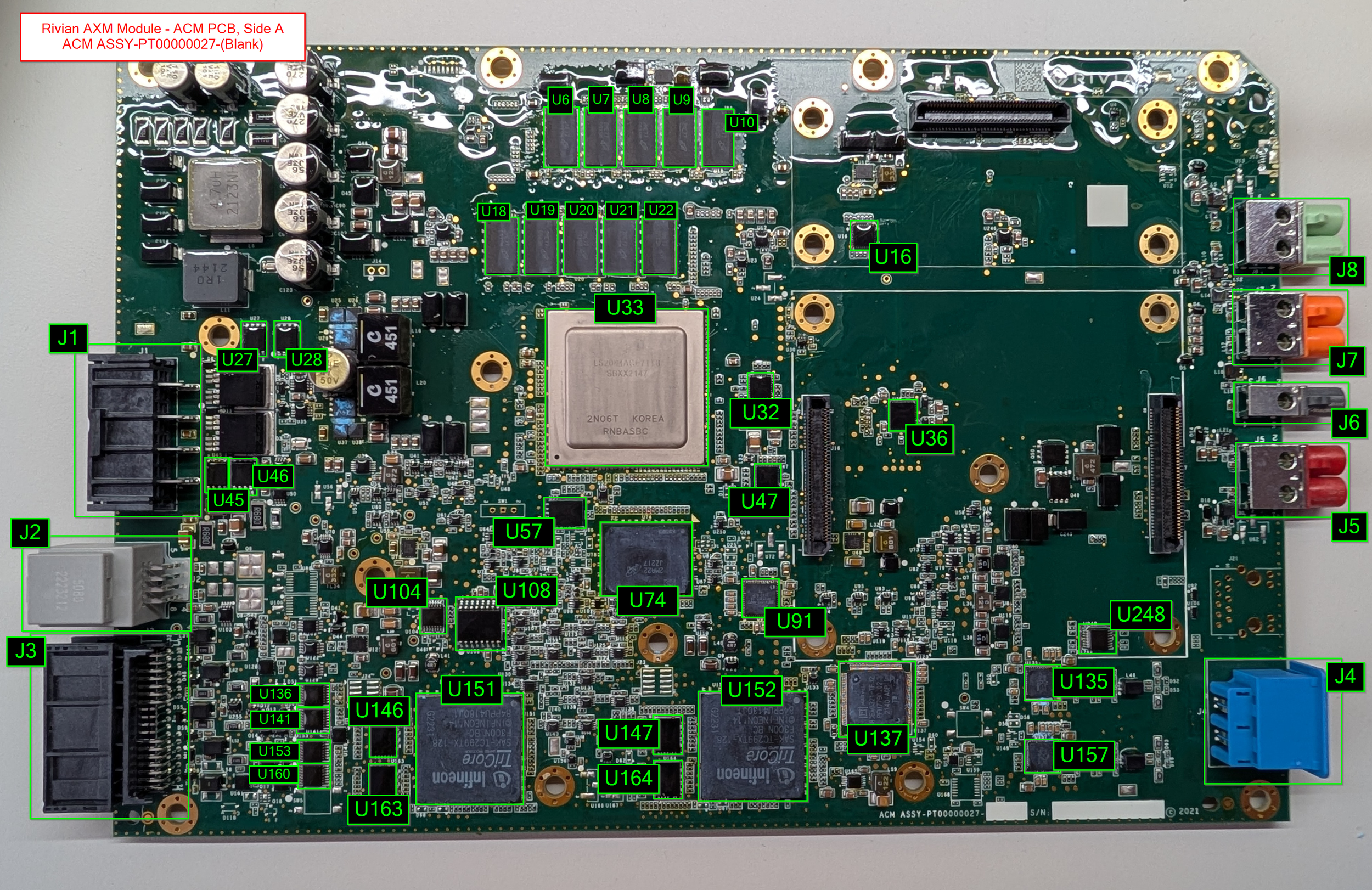
The ACM PCB, Side A.
Next up is the ACM PCB! The ACM controls a majority of the vehicle's ADAS functionality, along with its two daughterboards: The VLM, and the VPM.
The main processor on this board is an NXP Layerscape 8-core ARM Cortex-A72 Microcontroller, strapped with 10GB of RAM! Dual TriCore TC299 microcontrollers flank the bottom edge of the board, and the two image processing daughterboards occupy the right half of the PCB.
Board Markings - Side A:
ACM ASSY-PT00000027-(Blank)
S/N: (blank)
(C) 2021
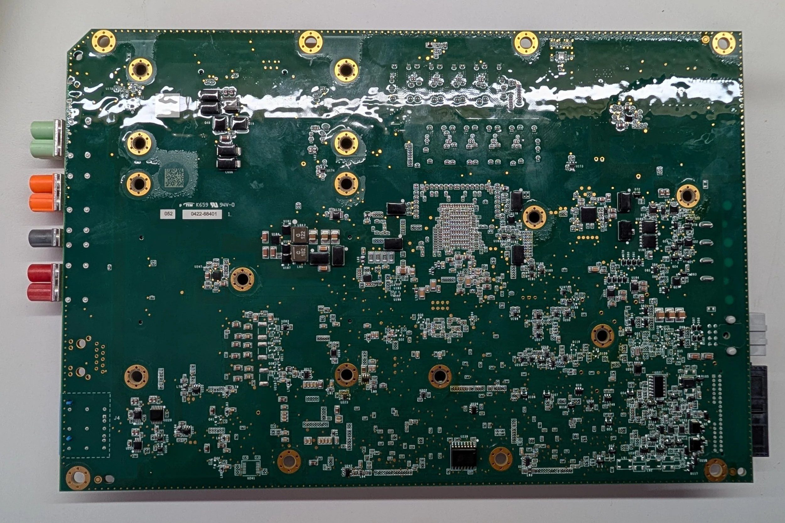
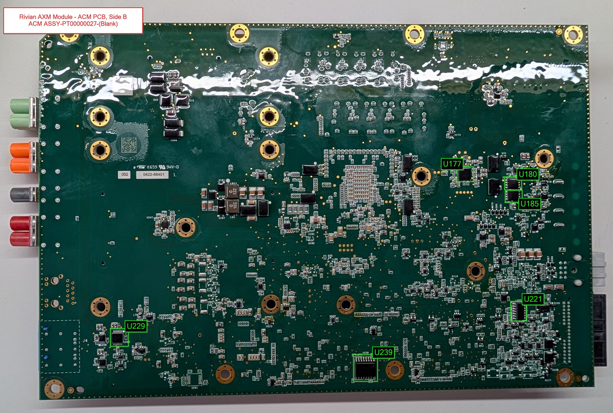
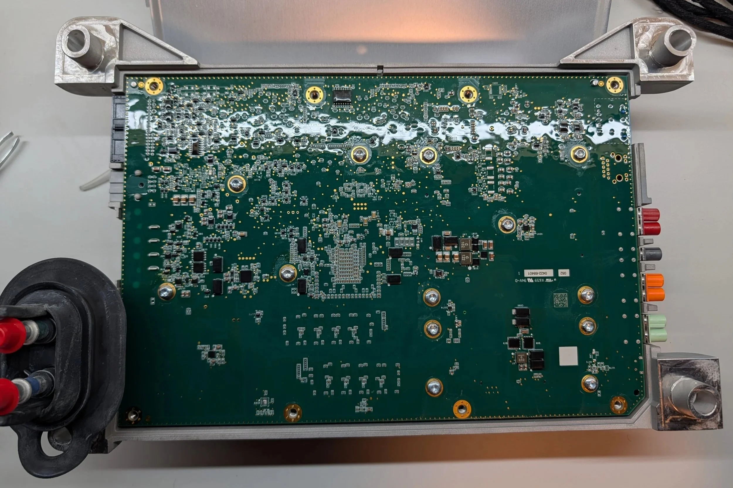
The ACM PCB, Side B.
The back of the ACM PCB is pretty uneventful - lots of small components for managing power and signalling and whatnot.
Board Markings - Side B:
K659 94V-0
052 0422-68401
ACM - Connectivity
For the ACM PCB’s connectivity, there’s quite a bit of camera and sensor data!
Dual gigabit ethernet
Multiple CAN buses
Driver monitoring system
Fender camera feeds
Surround camera feeds (between the ACM and XMM)
Front camera feed
Mirror/wing camera feeds
Overall, about what you’d expect from a board with 3+ dedicated video processing SoCs!
ACM - Component Overview Diagrams
As with the other PCBs, these diagrams aim to label a majority of the notable components present on the PCB.
ACM PCB, Side A - All components labeled
ACM PCB, Side B - All components labeled
ACM - Major Components
The list below has the main components found on the ACM PCB. Note: This is just for the main ACM PCB itself - the two daughterboards have their own sections below! And as always, for a list of all of the components I've identified, check the Appendix at the bottom of the post!
Processors
NXP Layerscape 64-bit 8-core ARM Cortex-A72 Microcontroller (datasheet)
LS2084ACE7TTB
SBXX2147
2N06T KOREA RNBASBC
Has 10GB of Micron DDR4 SDRAM
2x Infineon AURIX TriCore TC299TX Microcontroller (datasheet)
TriCore SAK-TC299TX-128
F300N BC
INFINEON 14
84PPU4180J1
Each have 16MB of ISSI SRAM
Storage
Micron 512GB PCIe Gen 3 NVMe TLC SSD (datasheet)
Micron 2MA22 JZ217
Decoded part number: MTFDHBL512TDQ-1AT12ATYY
2000 MB/s sequential read
1800 MB/s sequential write
Micron 1Gb (125MB) Serial NOR Flash (datasheet) (datasheet 2)
ISAI7 RW249
Decoded part number: MT25QU01GBBB8E12-0AAT
Infineon/Spansion 128Mbit NOR Flash (datasheet)
FL128SAMF00
264QQ062 A
11 SPANSION
Networking
Marvell/Infineon BRIGHTLANE 10/100/1000 Mbps Ethernet Transceiver (datasheet) (datasheet 2)
Marvell 88EA1512-NNP2
PFX1800.28
2147 B2P TW
Despite being branded Marvell, it seems like this specific product is an Infineon product?
2x Marvell Automotive Ethernet PHY (datasheet)
Marvell Q2112-NYD2
TGFF15 17
2202 A2E
TW
100/1000BASE-T1 (100mbit -> 1gbit auto ethernet)
Infineon/Marvell 7-port Unmanaged Automotive Ethernet Switch (datasheet) (datasheet 2)
Marvell 88EA6321-TF J2
PFM7790 02
2140 A0P TW
Sensors
Murata Manufacturing SCC3000-series X/Z-axis Gyro & 3-axis Accelerometer (datasheet)
SCC3134-D11
24521015FCC30
"SCC3000 is targeted at safety critical applications" such as electronic stability control, dynamic chassis control, lane-keeping assistance, etc.
Based on the part number being similar to the SCC3134-D10, I'm pretty sure this would have a 1-axis gyro and 3-axis accelerometer. Couldn't find any exact info on the D11
VLM Daughterboard PCB
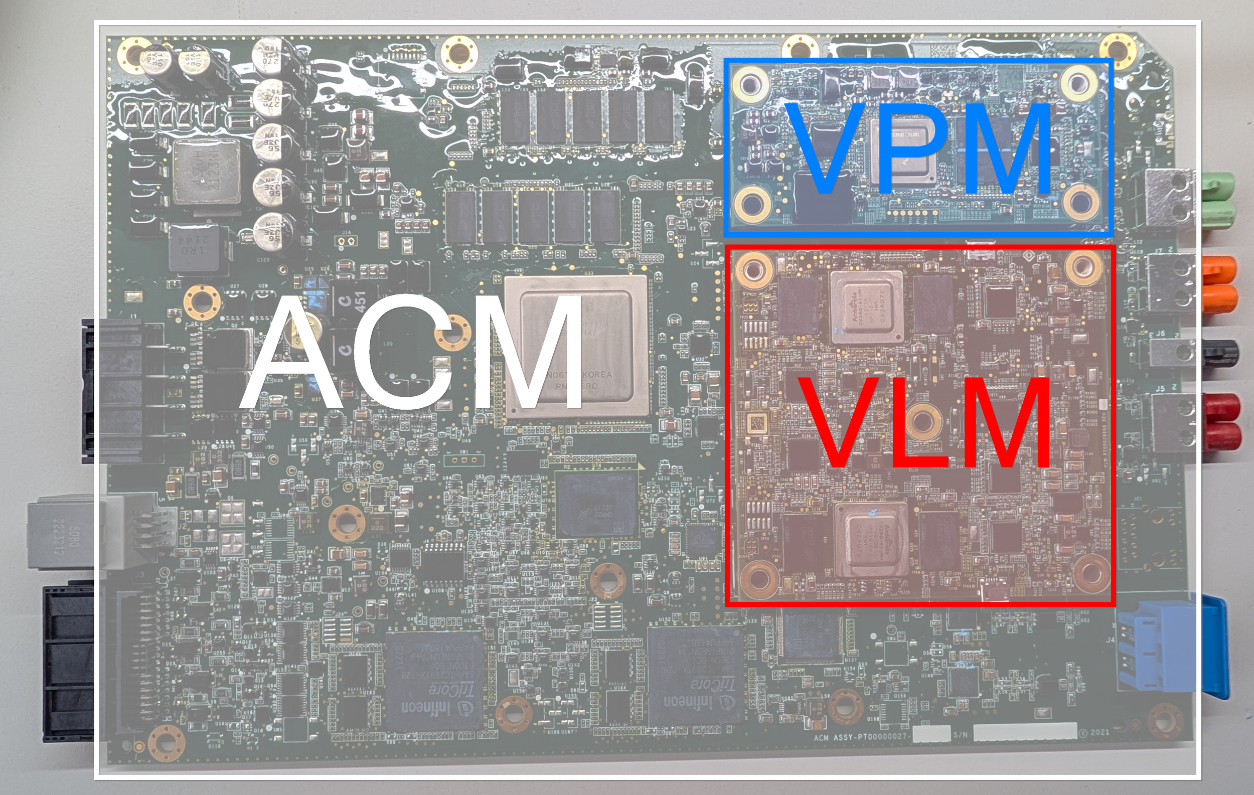
The full ACM board, with the VLM PCB highlighted in red.
The VLM PCB is the square-shaped daughterboard present on the ACM module. This PCB is mainly used for processing the video data transmitted by the mirror/wing cameras, as well as the front-facing long-range camera.
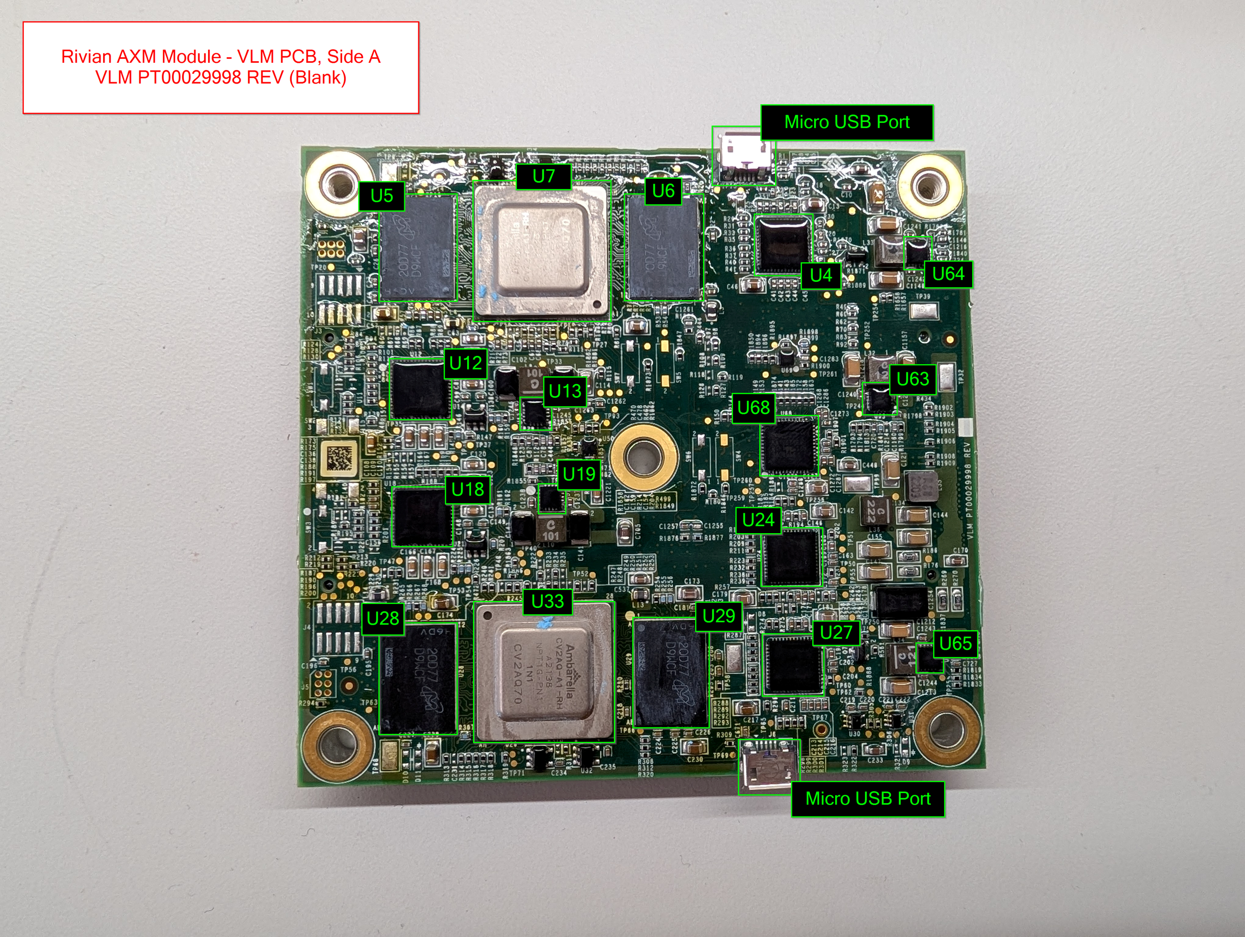
A close-up of the VLM PCB, side A.
The board is almost symmetrical, featuring dual Ambarella camera processing SoC with 4GB of LPDDR4 RAM each. Interestingly, the board also features dual Micro USB ports - possibly a left-over debugging interface?
Board Markings: VLM PT00029998 REV (Blank)
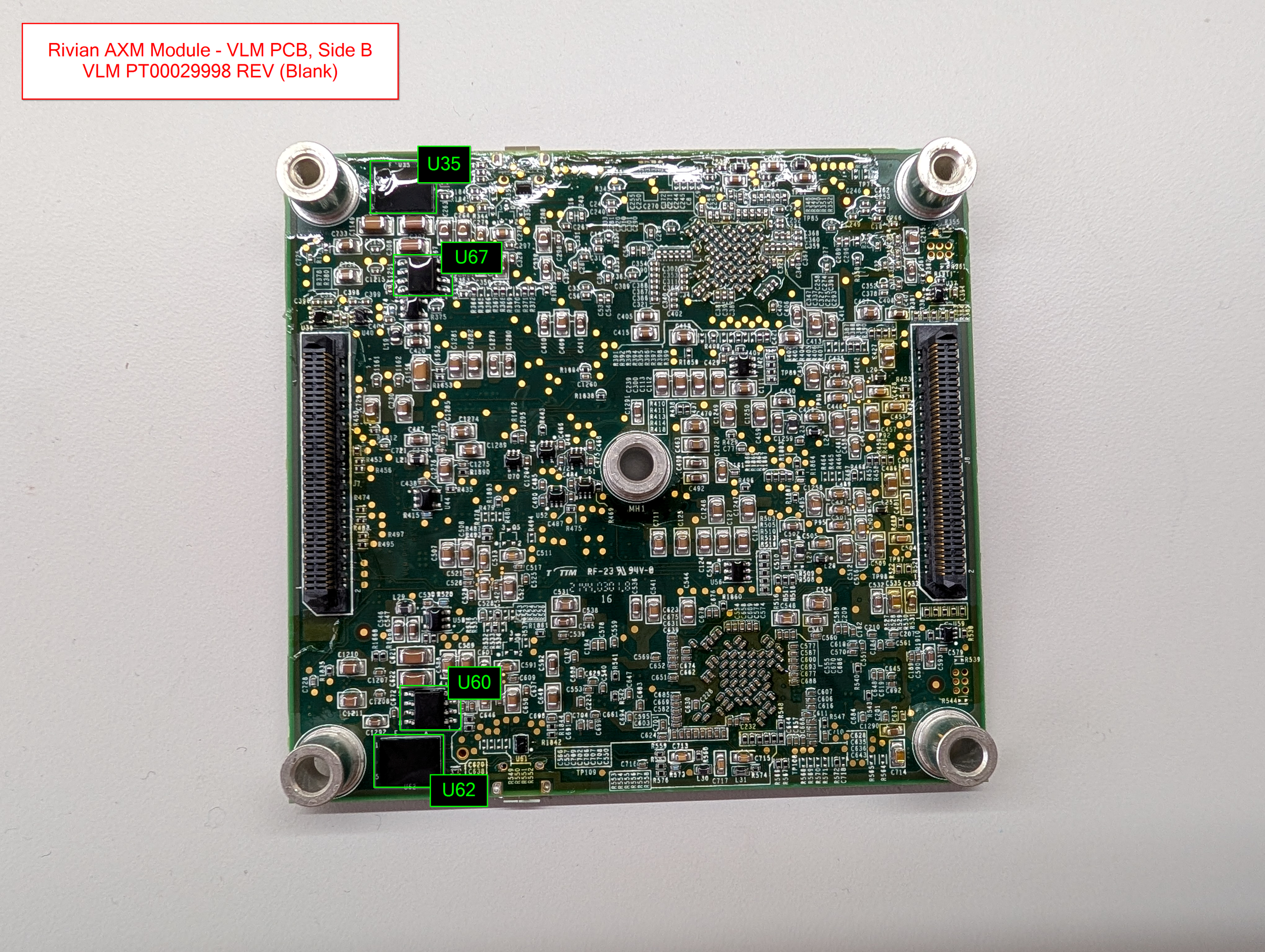
Side B of the VLM PCB, showing the two large connectors.
The back of the board is quite dense, but light on interesting components. The dual Micron 125MB Serial NOR flash chips on the left side of the board are interesting, I’m not sure what they contain (yet). Maybe storage for the Ambarella chips up top? It’s hard to say, as the Ambarella SoCs don’t have much public documentation.
VLM - Connectivity
The VLM’s PCB is pretty straightforward, connectivity-wise:
Two large socketed connectors are mounted on the left and right underneath the board to allow connectivity to the ACM
Dual Marvell Ethernet transceivers
Three FPD-Link III Video Deserializers
One GMSL2 to CSI-2 Deserializer
VLM - Component Overview Diagrams
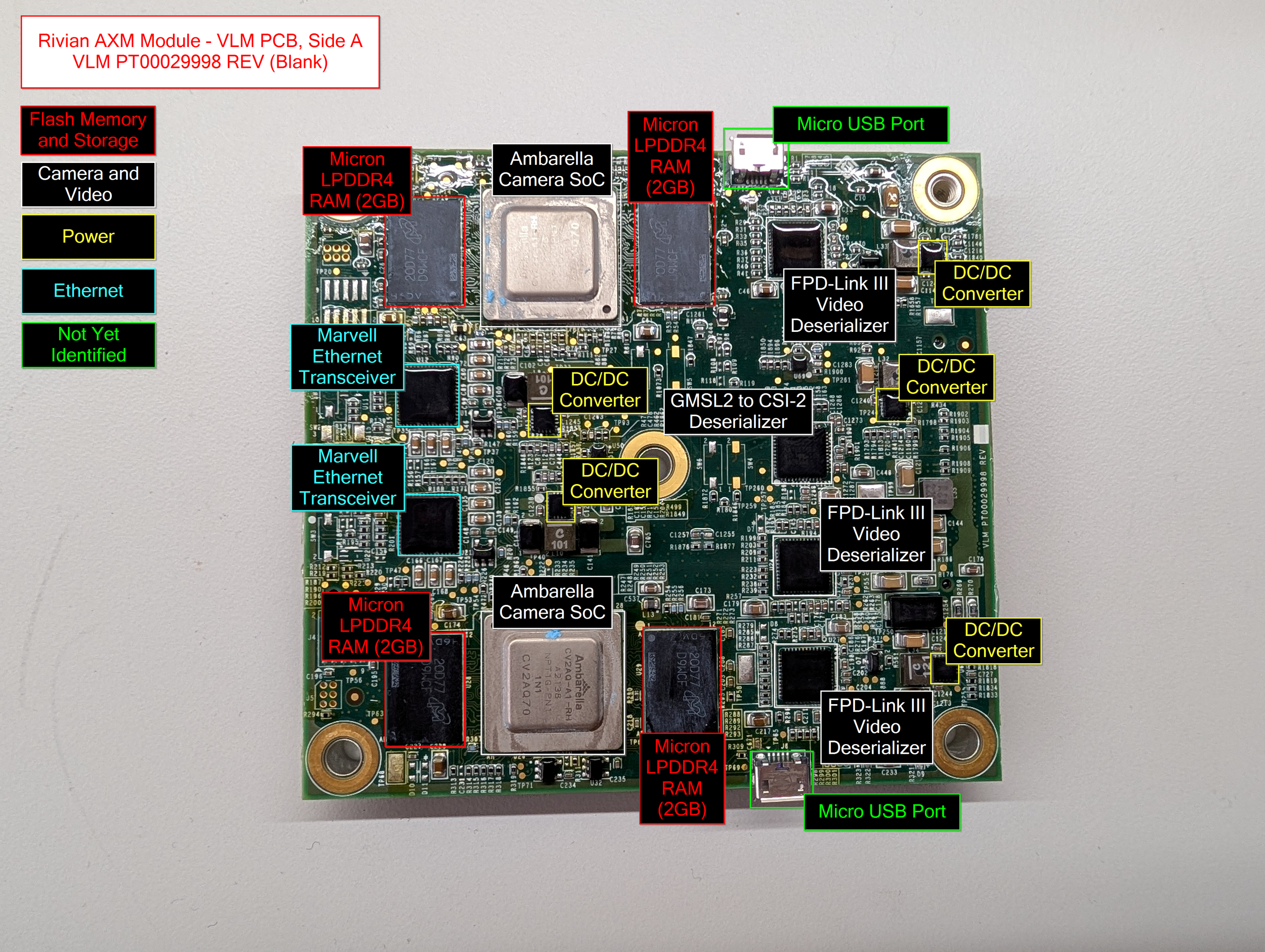
VLM PCB, Side A - Components Labeled
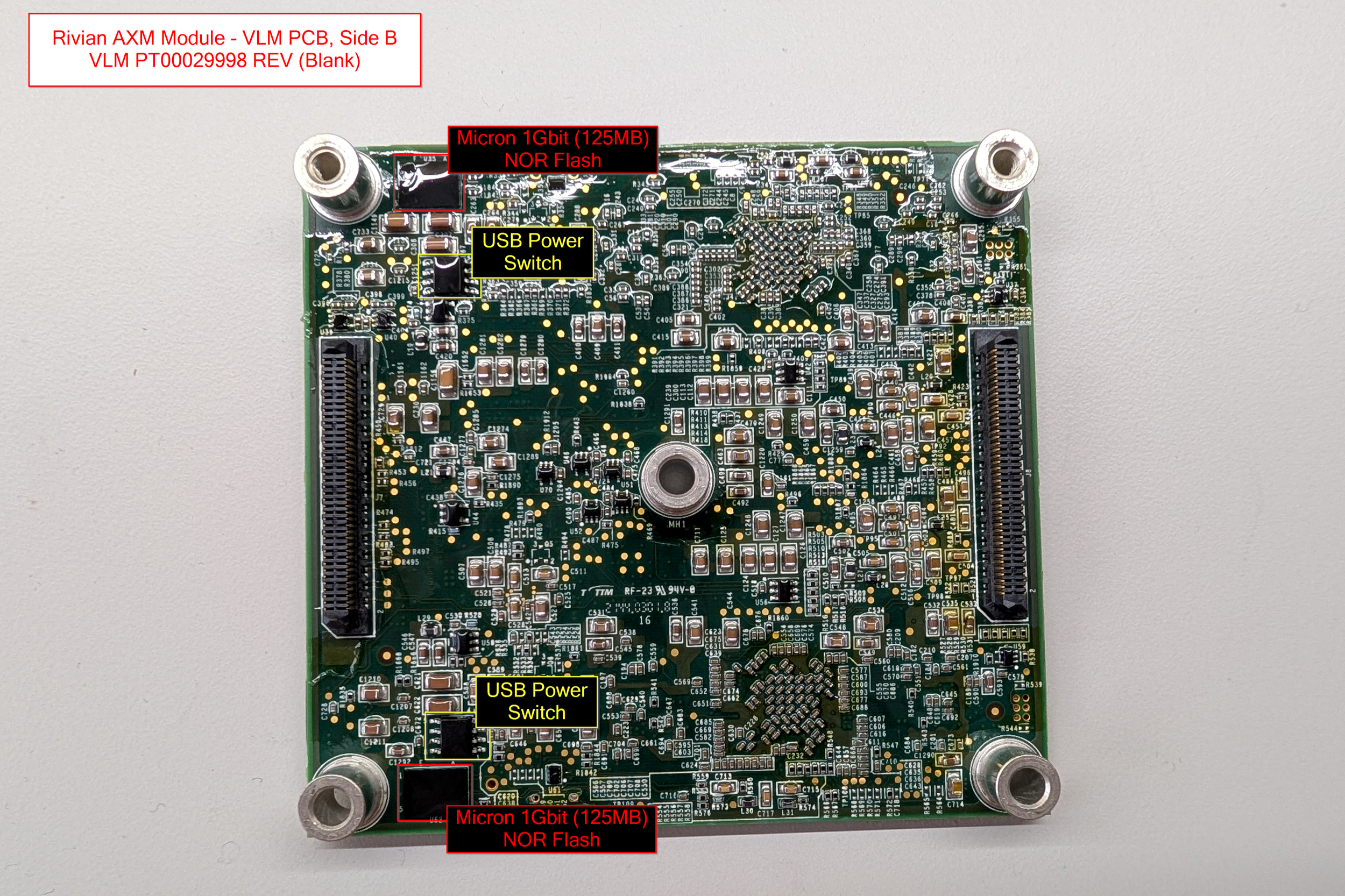
VLM PCB, Side B - Components Labeled
VLM - Major Components
Processors
2x Ambarella Camera/Vision Processing SoCs (datasheet)
Ambarella CV2AQ-A1-RH
A2138 NPT1G-PN1
1N1 CV2AQ70
Unfortunately not much public data online about these chips, no datasheets.
4GB of Micron LPDDR4 RAM each
Storage
2x Micron 1Gb (125MB) Serial NOR Flash (datasheet) (datasheet 2)
IXAI7 RW249
Decoded Part Number: MT25QU01GBBB8E12-0AAT
Networking
2x Marvell/Infineon BRIGHTLANE 10/100/1000 Mbps Ethernet Transceiver (datasheet) (datasheet 2)
Marvell 88EA1512-NNP2
Despite being branded Marvell, it seems like this specific version is an Infineon product
Video
3x TI Dual FPD-Link III Deserializer Hub with MIPI CSI-2 Outputs for Cameras and RADAR (datasheet)
UB954Q
TI 28I
C8K2 G4
Analog Devices Dual GMSL2 to CSI-2 Deserializer (datasheet)
MAX96716A
GTM/V 148
BACCSAS
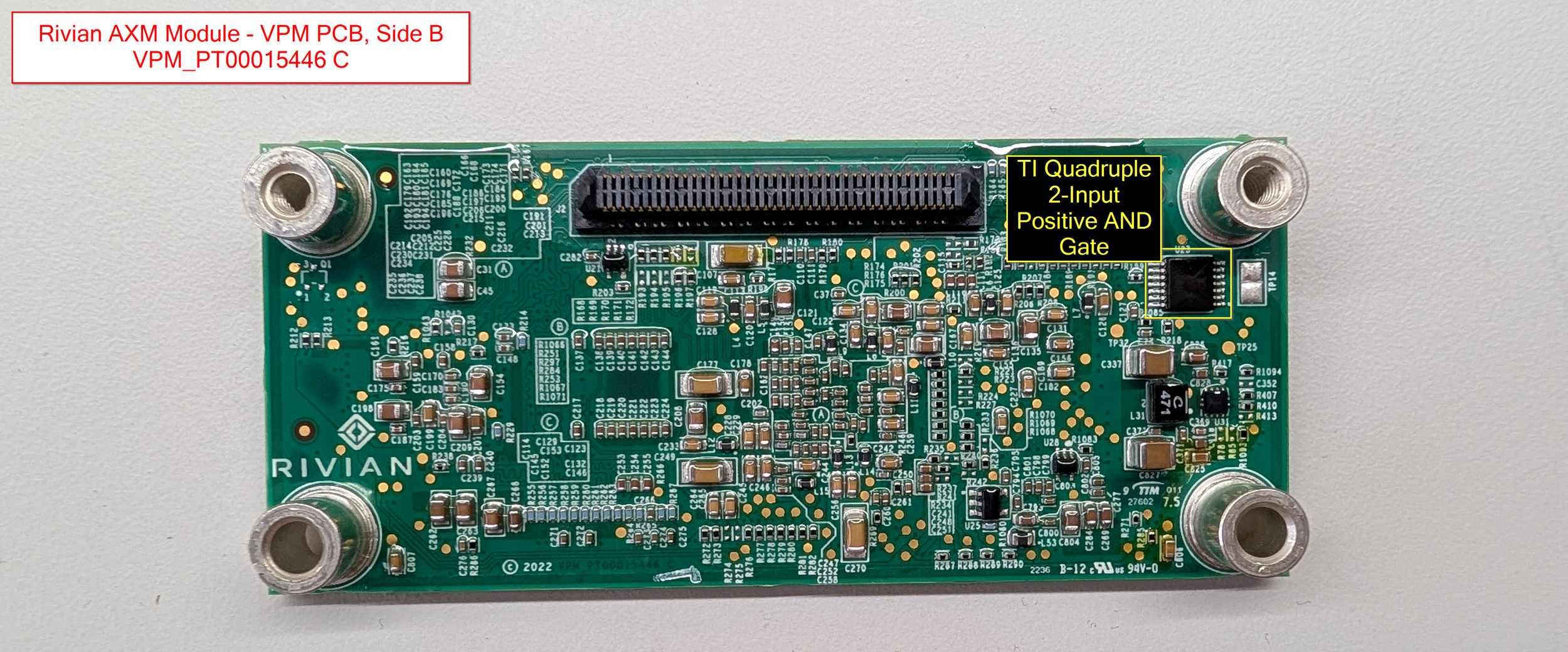
VPM Daughterboard PCB
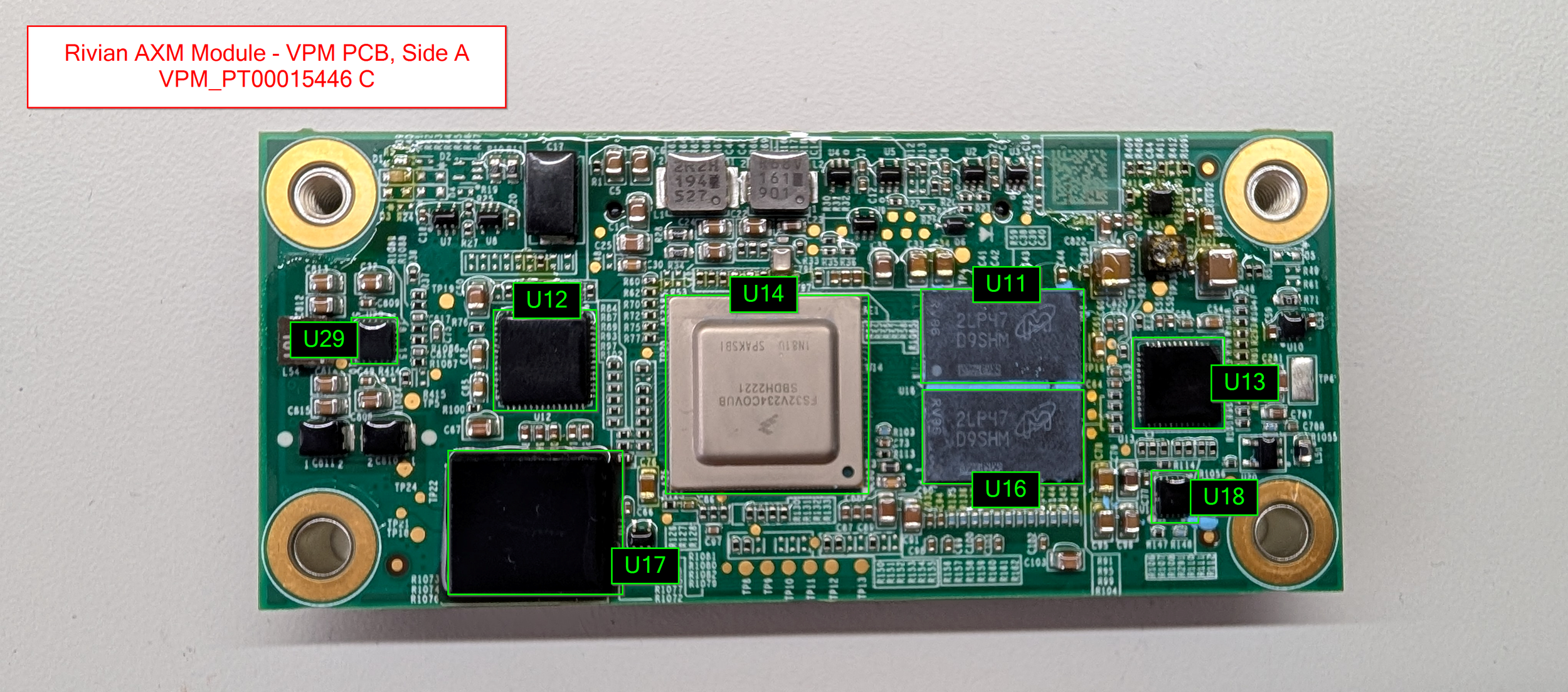
The VPM PCB is the smaller rectangular daughterboard present on the ACM PCB. As with the VLM PCB, this small board is also intended for the processing of video data! This board is mainly responsible for processing the video footage from the fender cameras on the vehicle.
Board Markings: VPM_PT00015446 C
The components present are pretty simple - an NXP S32V234 ARM processor, 1GB of DDR3 RAM, and 8GB of eMMC flash storage!
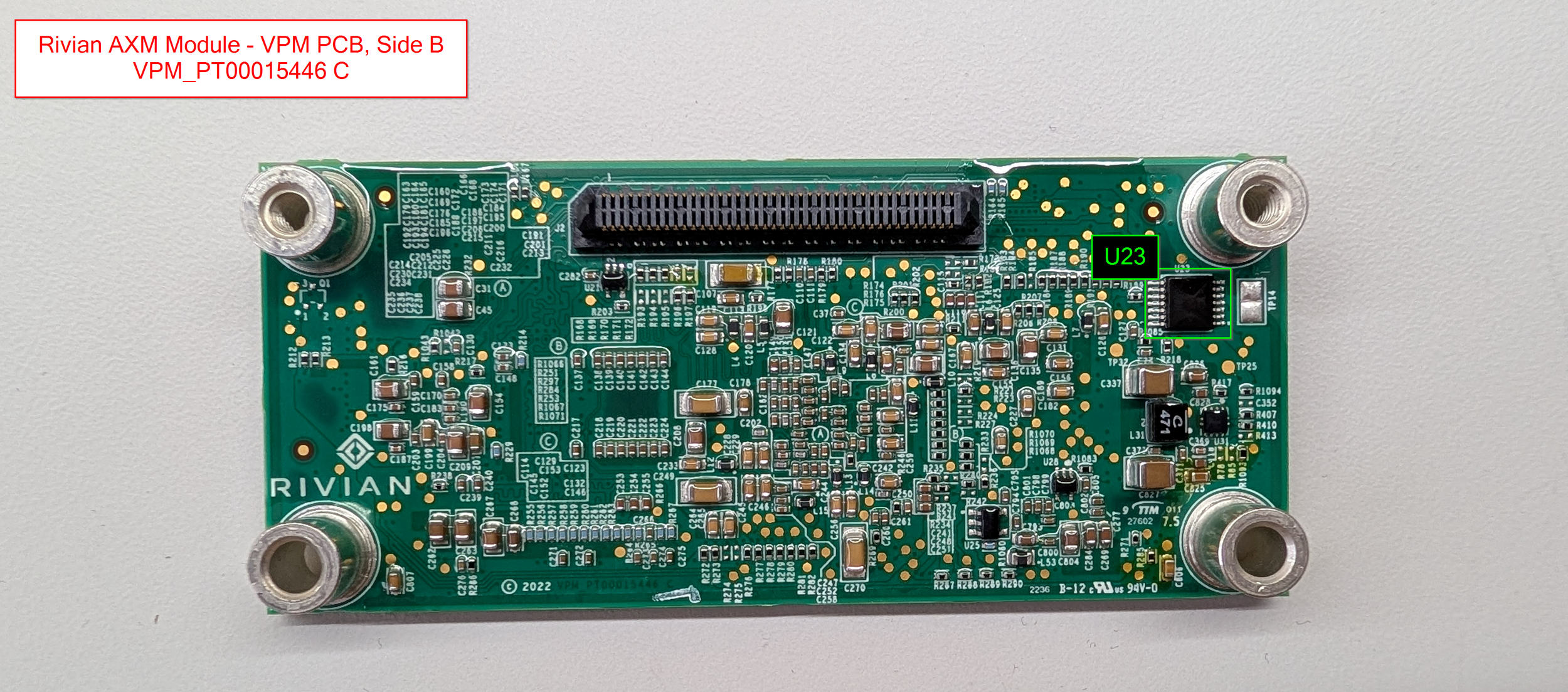
Basically nothing of note going on underneath - just a lot of complicated resistor and capacitor layouts!
VPM - Connectivity
For connectivity, we really only have two buses of note on this PCB:
10/100/1000 Ethernet Transceiver
FPD-Link III Deserializer
So, just ethernet and video. Easy!
VPM - Component Overview Diagrams
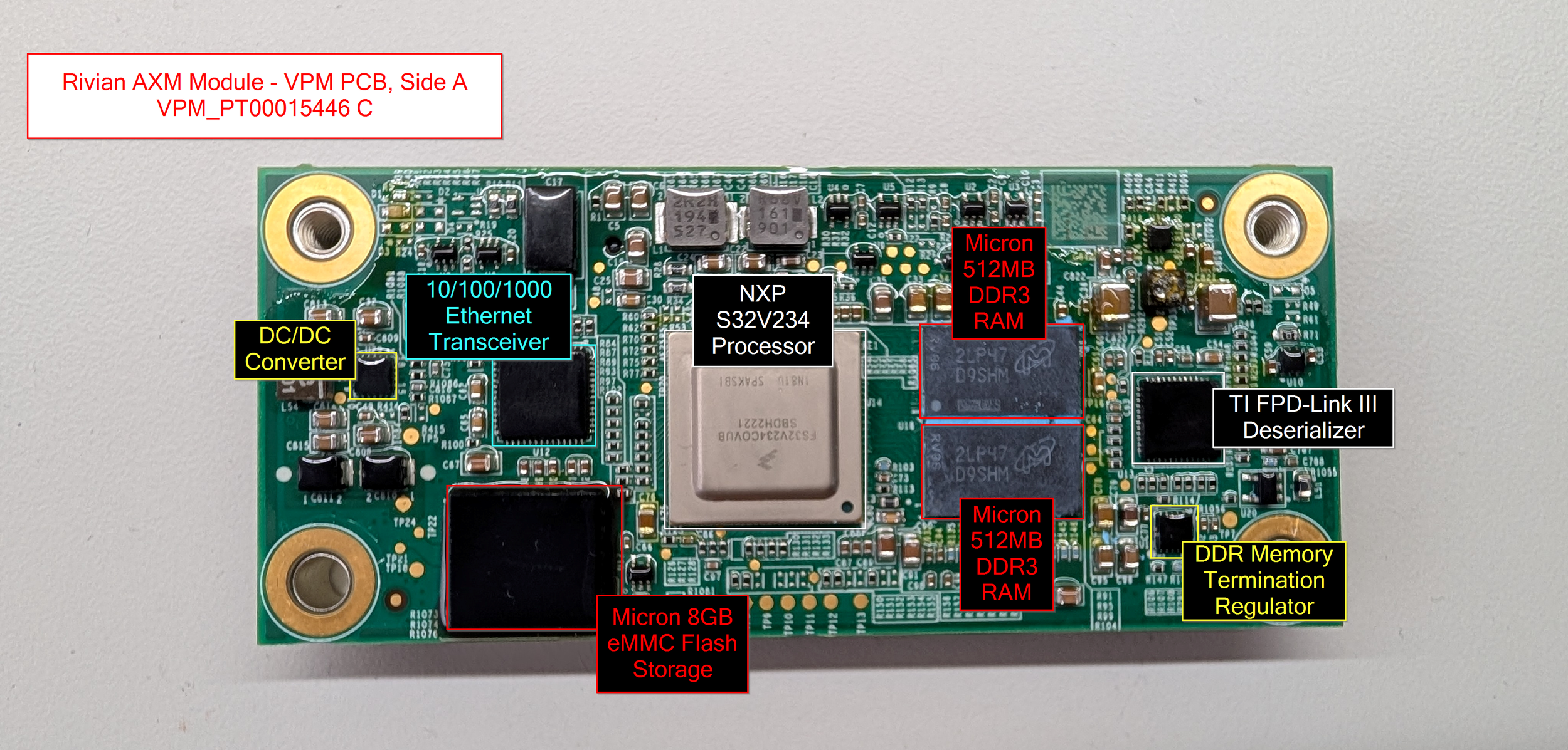
VPM PCB, Side A - Components labeled.
VPM PCB, Side B - Components labeled.
VPM - Major Components
The below list contains the most interesting major components on the VLM. As always, the full list of all identified components lives down in the Appendix!
Processors
NXP S32V234 Quad-Core ARM Processor (datasheet)
"S32V MPUs for Front/Surround View Camera, Computer Vision"
1x ARM Cortex-M4, 4x ARM Cortex-A53
FS32V234COVUB
SBDH2221
1N81U SPAKSBI
Paired with 1GB of Micron DDR3 RAM
Storage
Micron 64Gb (8GB) eMMC Flash Storage (datasheet) (datasheet 2)
2OA2D JWC63
Decoded Part Number: MTFC8GAMALBH-AAT
Networking
Marvell/Infineon BRIGHTLANE 10/100/1000 Mbps Ethernet Transceiver (datasheet) (datasheet 2)
Marvell 88EA1512-NNP2
PFX1800.28
2147 B2P
Despite being branded Marvell, it seems like this specific version is an Infineon product
Video
TI Dual FPD-Link III Deserializer Hub with MIPI CSI-2 Outputs for Cameras and RADAR (datasheet)
UB954Q
TI 27I
AVHK G4
Conclusion & Future Plans
That's it for this module! I hope you enjoyed the teardown.
In the future, I'd love to dump some of the on-board flash chips and do some high level writeups about the device’s firmware. Currently, I’m just split on whether I want to turn my working unit into a non-working one… I need to practice my reballing skills before I pull off any chips! lol. Also, there are quite a few JTAG headers and debug pinouts available on the board - it could be interesting to see what’s enabled vs. disabled there…
As always, thank you for reading! If you have any questions or feedback, please feel free to reach out - I'm always happy to chat!
And the eternal MOTD: Do it for fun, or don't do it at all. Happy hacking!
Appendix
As always, the appendix here holds the footnotes, side comments, and raw data dumps that I didn’t want to include in the main body of the blog post above. Enjoy!
Yellow Heading Color: #ffd300
Rivian Stickers/Labels
Top Label Contents
PT00001493-M
22282 | 000137
2022.31.02
R1T | ACM
Inspection Label Contents
R1 2022.31.02 | a44b8447
Initial Inspection, LS2, XMM, ACM, Final Inspection
Full Component Listings
In the main section of the article, I pared down the list of components to a high-level overview of major components so that it wouldn’t make the post un-readable. That being said, in a mission to identify all of the major chips on each PCB, I actually have much more detailed info! The full lists include non-security-relevant pieces like the various voltage regulators, bus transceivers, MOSFETs, and other random ICs that I identified on each of the boards.
I’ve put all of the information into markdown files on my GitHub, available here: https://github.com/ttepatti/teardown-rivian-axm-1.0
(I would’ve included it all here but it’s hella lines of bulk text, so I figured it was better off on GitHub)
Even though the info isn’t very security-relevant, I figured I might as well publish it since I’ve already collected it all. Enjoy!
Thoughts on Conformal Coatings
As you might be able to tell by the teardown photos, all of the boards in the AXM 1.0 are covered in a conformal coating of some sort. It’s not outwardly sticky, but it does scuff and take fingerprints quite easily, so it’s at least somewhat malleable.
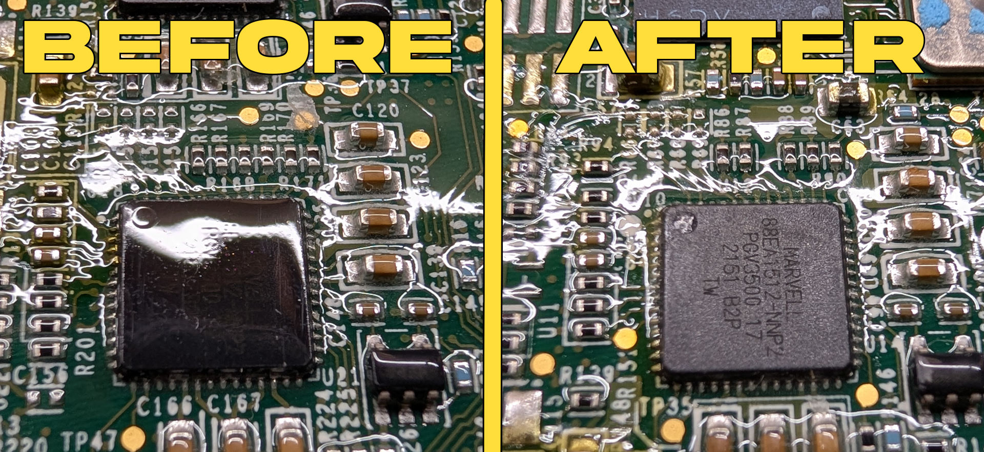
At first, I was taking my PCB photos by using a flashlight and my phone’s macro camera to see through the reflective conformal coating. But when I got to the VLM and VPM PCBs, it was impossible. I’m not sure why, but the conformal coating on these ICs seemed to be much thicker, obscuring basically all of the part numbers!
I’ve never removed conformal coating before, but after a bit of Googling, I landed on a pretty basic method: Heat gun set to 100-150C, and a sharp knife! (Or, in in my case, an iFixit metal scraper thingy)
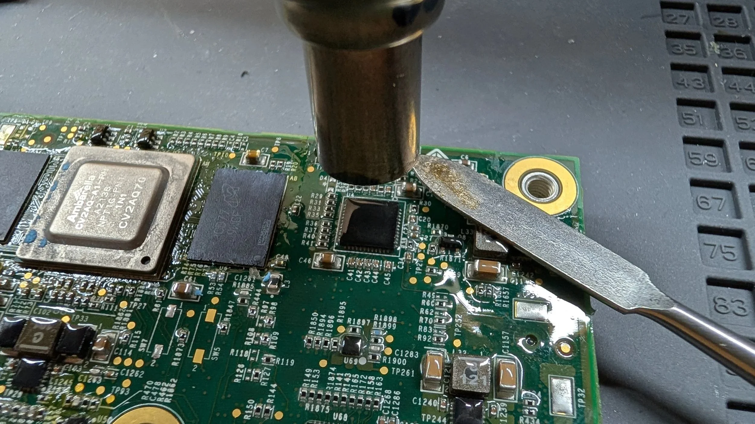
I ended up with my heat gun at 175C, but this worked great, albeit a bit slowly. I was able to remove the conformal coating from the top of each IC, making them far easier to photograph. Check out this comparison!
I figured it might be worth adding that as a footnote here in case anyone is looking for tips on scraping the conformal coating off one of these modules during repair or whatnot. Fair warning, I didn’t scrape off any of the pins yet, so I’m not sure how this technique would fare for that…
Silkscreen IC Marking Diagrams
Before I labeled each of the PCB diagrams, I first laid out an initial diagram using the IC markings on the board. So for example, the Micron RAM on the ACM PCB is actually marked U67 through U10 on the PCB silkscreen. I included this info in the below “full component listings” for each of the PCBs, so I figured I might as well throw these diagrams out there as well. Hopefully someone can get some use out of ‘em, since I already put them together. Enjoy!